Q&A Report: The Wonderful World of Scanning Electrochemical Microscopy (SECM)
These answers have been provided by:
Janine Mauzeroll, PhD
Professor of Chemistry
McGill University
Mareike Haensch, PhD
Application Scientist
HEKA Elektronik
Frank Wang, PhD
Senior Applications Scientist
HEKA Elektronik
What is the closest you can approach a cell membrane without contacting it?
J. Mauzeroll: SECM instrument typically have a minimal step size that depends on the type of high positioning motors chosen for this instrument. In our system the minimal step size is 5 nm. Theoretically you could say that the closest approach distance prior to contact would be 5 nm.
In practice, reaching the theoretical approach limit rarely happens because your sample surface is often inherently tilted or the microelectrode/micropipette that you are using may not be perfectly flat. A such your practical minimal approach distance may be far greater than 5 nm. Often times you can observe tip to surface contact during an approach curve as a sudden change in slope at short tip-to-substrate distances.
Can we use SECM for biosensor studies using screen printed electrodes as a substrate?
M. Haensch: Electrochemical cells for SECM are often sandwich cells which allow the study of many different sample geometries. You can mount the (modified) screen printed electrode into such a cell. With SECM, you can now study e.g. the homogeneity of the electrode modification and its local electrochemical activity.
What are the similarities to SVET (Scanning Vibrating Electrode Technique)?
J. Mauzeroll: SVET uses a three-electrode setup to measure and map potential gradients generated at an immersed electrochemically active surface (working electrode) through the vibration of an electrode (counter electrode, normally made of Pt−Ir alloy (> 15 μm)) in solution. This technique was initially developed for extracellular measurements on biological samples and due to its benefits of spatially resolved processes, SVET was introduced into corrosion science.
SVET measures current densities as small as 5 μA cm−2 through the oscillation of the tip at a specific vibration amplitude (A in m). A potential drop (ΔE in V) is measured and can be converted to current densities (j A m−2), assuming knowledge of the solution conductivity (σ S m−1).
SVET remains indispensable for galvanic corrosion measurements due to its ability of expressing surface damages in terms of local corrosion rates that can be addressed by predictive numerical models and compared to bulk corrosion rates. More info can be found here: Anal. Chem. 2015, 87, 15, 7499–7509
Is SECM sensitive to ions (e.g. Ca2+), and can it estimate local ion strength in situ?
M. Haensch: Special ion-selective potentiometric electrodes can be fabricated to detect and quantify specific ions in solution. They are not commonly commercially available but have to be fabricated in your lab. In certain commercial systems that combine SECM with an inverted Fluorescence microscope, calcium ions can be labelled with ratiometric dyes, thus allowing in-situ imaging of calcium ion concentration by Fluorescence intensities while using SECM or SICM probes to stimulate or measure various current/voltage signals of interest.
Is it possible to automate the movement of the probe in all 3 directions without need to pay attention continuously during the measurements?
J. Mauzeroll: Yes. Most commercial and home-built instruments have to possibility to implement batch mode measurements.
If we want to use SECM using SG/TC mode how do we know/distinguish the current that we got is the current from SG/TC instead of the current from feedback or bulk diffusion?
M. Haensch: Usually, in generation/collection mode you want to detect a species which is generated at the substrate but is not present in solution before. One example is the detection of oxygen from water splitting catalysts in deaerated NaOH solution. The potential at the microelectrode is set to a value to reduce the oxygen to OH-. At this potential, no other species in the solution should show a reaction. This can be tested by running a CV far from the surface. The current you measure close to the surface is ideally solely due to the generation of species at the substrate. You cannot avoid that diffusion of the generated species takes place. This is a blurring effect in SECM which lowers the spatial resolution of the experiment. You should keep that in mind. But generally, this is not a problem for the analysis of the results. Features in SECM can appear a bit larger than they really are.
In comparing SECM with SMCM (scanning micropipette contact method) techniques, what are the advantages of micropipette-based SMCM techniques?
J. Mauzeroll: The main advantage is that you control the time at which a sample is exposed to the test solution. You can imagine that for a corroding sample this becomes important if you want to compare the electrochemical response between spots. In an SECM experiment, the last point in your scan would have been exposed to your test solution for a greater amount of time than the first couple of points. It could be coverage with more corrosion product and have a very different reactivity.
Another advantage of SMCM is that it is pretty straightforward to cross-correlate the region that have been investigated by SMCM with post-mortem electron microscopy measurements.
Is the scanning droplet cell microscopy pretty much the same as SMCM, with the only difference being having a reservoir of solution to tackle solvent evaporation?
M. Haensch: The biggest difference between the two techniques is the droplet size and therefore spatial resolution of the measurement. Commonly, the scanning droplet cell has an opening of > 100 µm and is therefore much bigger than the opening of a micro- or nanopipette with 1 µm – 50 nm. The pipettes can therefore be used to achieve micron-scale or even nanoscale mapping of surfaces. Two examples are grain boundary mapping and the mapping of single nanosheets or flakes. The evaporation in SMCM can be a problem due to the small pipette opening, because even the smallest crystals can block the entry. This can be avoided by making sure the surrounding environment has enough humidity. Either by placing a humidifier in the lab or by simply placing a wet paper towel around the electrochemical cell. To further avoid formation of salt crystals, usually low electrolyte concentrations are used.
In SECM imaging is there any rule of thumb for the maximum scan speed that can be used to avoid convection effect?
J. Mauzeroll: Yes, if the approach curve speed or imaging scan rate exceeds 5 µm/s, you can expect that forced convection effects will affect the recorded current.
More information can be found: Anal. Chem. 2012, 84, 8, 3531–3537
Is there a convenient way to perform tilt correction?
M. Haensch: Means for tilt correction are always included in a SECM setup. HEKA solves the issue of tilt by having a software-based tilt correction which is easy to use. While scanning along one axis, the additional z piezo will either lift of lower the probe continuously according to the settings to eliminate the sample tilt.
How might you combine atomic force microscopy (AFM) with SECM?
M. Haensch: A combined AFM-SECM is commonly based on the AFM platform. For SECM functionalities, special probes are used. The advantage is the higher resolution of the measurements due to the AFM tips. Disadvantages are the very limited scan area, high price of AFM probes and limited possibility to fabricate them on your own and the simulation of results are harder to do due to more complex tip geometries.
You showed a few different types of probes – are any of them easier to prepare for beginners? And do you know which ones are commercially available?
J. Mauzeroll: Most probes that are commercially available are disk-shaped in geometry. You can also find conical probes. The easiest probes to implement are disk shaped. The exact protocol varies greatly between groups.
In our team, we have been using the following protocol for years: Anal. Chem. 2015, 87, 5, 2565–2569
How can you use the current to measure electrical properties or morphology (i.e. height)?
F. Wang: In SECCM/SMCM technique, the first step of a hopping scan cycle starts from approaching the tip to sample surface while applying a small bias potential between the QRCE placed inside the nanopipette tip and the sample working electrode; as soon as the nano-droplet (from the tip) lands on the sample substrate, the SECCM system detects a sudden change in tip current and records the Z-axis height (i.e. the topography height). And the next step in workflow is to hold the tip position and run a series of electrochemical measurements (e.g. local charging/discharging, etc.) In this way, the topography height and electrical properties are recorded and separated in different stages at each scan point.
How do you subtract two images? What of software processing tool(s) do you use?
J. Mauzeroll: Most students will write their own Matlab or Phyton script. Currently we are working on open-source software that you can download and use for your own experiments. We call it Flux. Flux is free, open-source software developed in Python to simplify the processing of SECM data. It is designed to treat experimental data from a variety of instrument manufacturers for images, approach curves, cyclic voltammograms, and chronoamperograms.
The data treatment workflow is customizable and supports common tasks including normalization of currents, slope correction of images, and quantitative analysis. You can download it here: http://bioelectrochemistry.mcgill.ca/software.html, modify it and subtract SECM images.
How can you find the exact position of the probe in the SEM?
F. Wang: From practical point of view, samples used in SECCM/SMCM experiments should be kept fairly small in size (e.g. < 1 cm2). The micropipette tip used in SECCM/SMCM was often filled with diluted electrolyte solutions (e.g. 10mM ~ 50mM salt). Before the SECCM hopping-scan starts, user should try to find or purposely create a local surface reference mark (if possible, do this step with the help of a top/side-mounted camera used for viewing the tip/substrate positions), and allow the matrix type of scans to cover the pre-positioned local surface area. Once the scan finishes, the scanned local surface always has arrays of micro-droplet’s footprints left from trace amount of electrolyte salt crystallization. Therefore, when taking the sample in SEM imaging, it is fairly easy for users to locate the surface reference mark or directly find the arrays of micro-droplet’s footprints.
Do you silanize the pipette exterior for SECCM with oil layer?
J. Mauzeroll: We did not silanize the pipette’s exterior prior to the oil-immersed SMCM experiments. To produce the micropipettes, quartz capillaries of 0.3/1.0 mm ID/OD (Sutter Instrument, Novato, CA) were pulled to form two symmetrical micropipettes with apertures of ~1.65 μm diameter using a P-2000 CO2 laser puller (Sutter Instrument) operated from a single line heating and pulling program (Heat = 585; Fil = 2; Vel = 30; Del = 130; Pul = 30).
For corrosion experiments, the micropipette was filled with 3.5 wt% NaCl solution. An Ag/AgCl quasi-reference counter electrode (QRCE) (0.125 mm diameter Ag wire (GoodFellow Metals, Huntingdon, England)), was fabricated by soaking in bleach, rinsing in deionized water and then wiping clean. The wire was then inserted into the back of the micropipette and kept at a constant distance (~1.5-6 cm) from the micropipette tip. More information can be found (Analytical Chemistry 2020, 92, 18, 12415-12422)
Can direct electron transfer between the substrate and the microelectrode tip be observed? Or does the current need to be carried by a diffusing electroactive species?
F. Wang: For SECM, most common working modes require the mass transport of electroactive species present between the substrate and the microelectrode tip. For SECCM/SMCM, it is possible to detect electron transfer on the substrate directly without relying on the diffusion of redox mediators.
Provided a sufficiently sensitive potentiostat for current detection, can an SECM probe be too small? I've heard that some measurements lose meaning at very small tips but I don’t understand why this would be.
J. Mauzeroll: It comes down to the basic instrumental analysis question of signal to noise. Some potentiostat truly have ultra-low current capabilities and so you can measure fA currents with no difficulty. If your system has great electronics, is shielded properly to reduce noise and thermal drift, then small probes can be used, but it is always a trade-off between using smaller tips to get enhanced lateral resolution during imaging and reasonable signal-to-noise ratio.
Can SECM be used to distinguish the number of electrons transported (for example, 2-electron or 4-electron transport in ORR)? Also, can we distinguish the products?
F. Wang: In SECM Generation/Collection mode, the microelectrode tip can be held at one or multiple sensing potentials that are suitable to selectively oxidize or reduce the different by-products generated from the substrate in the ORR pathway. This working mode is similar to the traditional RRDE technique and, in addition, can provide 3D results in mapping the spatial distribution of electrocatalysis products/activities.
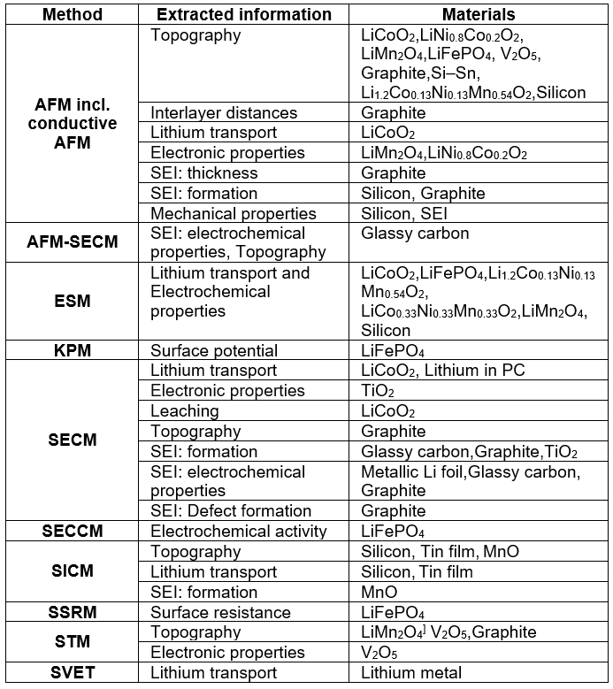
You described some research using micropipette-based methods to characterize batteries. Is there any nice battery research using normal SECM (not micro pipette)?
J. Mauzeroll: Yes. There are many groups worldwide that use scanning probe methods (including SECM) to study batteries. I have summarized a few examples in the table below and more information can be found: ChemElectroChem. 2016, 4, 6–19
What is the future of SECM?
F. Wang: This is no doubt a broad and meaningful question, concerning not only academic researchers, but also global SECM industry. As an Application Scientist from SECM industry, my observations in recent 5~6 years of SECM literature publications reveal the following hot trends in SECM research and development topics:
(A) Development of multifunctional probes (including those “nano-/micro-pipette” types for SECCM and SICM) and novel working/imaging modes, both of which make the collective SECM/SECCM/SICM techniques remaining to be the best in situ microscopy imaging tool for classical electrochemistry applications, such as: (1) renewable and clean energy, materials, and devices; (2) electrocatalysis in sensors; (3) corrosion and coating protections.
(B) Development of “hyphenated” electrochemical scanning probe techniques, which are targeting interdisciplinary research areas, such as: (1) single-cell and single-entity electroanalytical imaging and sensing (e.g. SECM-Fluorescence Microscopy Imaging); (2) in situ imaging of PEC (photoelectrochemical) materials/processes (e.g. scanning photoelectrochemical microscopy); (3) environmental sensing and remediations (e.g. SECM-Microspectroscopy).